Thermal-System-Basics
Home
Contact
Thermal System Basics
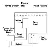
Thermal systems are easy to understand. A thermal system is typically made up of a workload, heater, temperature controller and temperature sensor. Figure 1 shows a simple water heating application using all four parts of the thermal system. Study it for a moment. The workload is the water being heated. The sensor is immersed directly into the water so it can accurately sense water temperature. The temperature control is controlling the water temperature by adding heat as necessary. The heater, of course, is providing the heat or thermal energy required to heat the water tank.
Note: Some thermal systems use only a workload, heater and controller. The controller only controls power flow to the heater. It does not control the workload temperature.
The workload is the material or object we want to heat up. The work load may be in the form of a solid (such as a metal block), liquid (such as water) or gas (such as air), or a combination of these. The figures below illustrate examples.
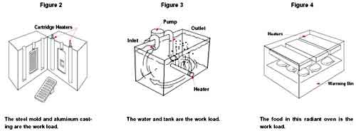
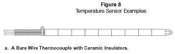
Look at Figure 3. Notice how heat generated by the heater goes immediately into the workload (water). Now look at Figure 2. To heat the aluminum casting, the heater must first heat the steel mold. Do you see any difference in this? Sure! The steel mold in Figure 2 functions as a heat transfer medium. It transfers the heat from the heater to part (aluminum casting). No heat transfer medium is required in Figure 3. The water is directly heated. A heat transfer medium transfers heat from the heater to the product in many conduction and convection applications. So actually, a workload can consist of two things:
1) The product made by the manufacturing process, and
2) The heat transfer medium (which transfers heat from the heater to the product manufactured).
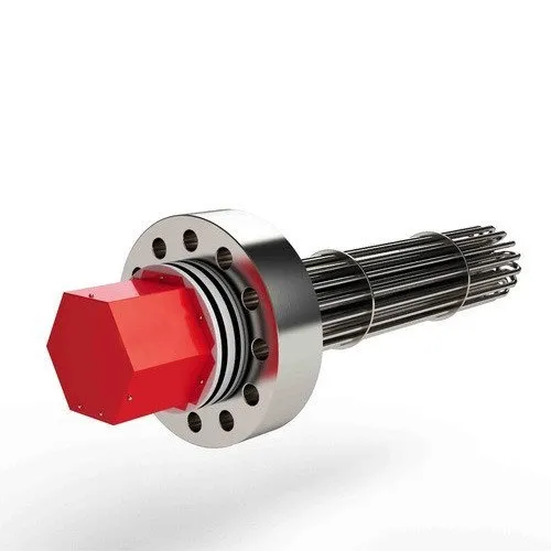
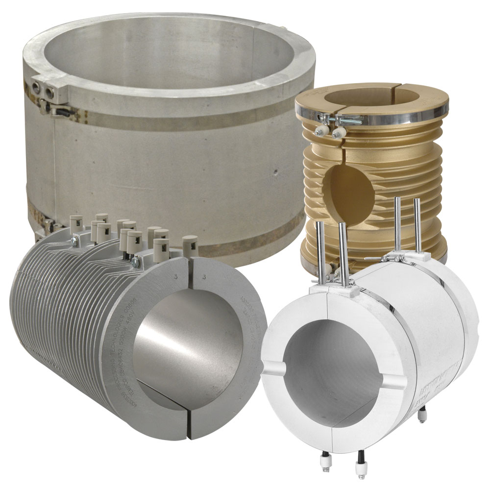
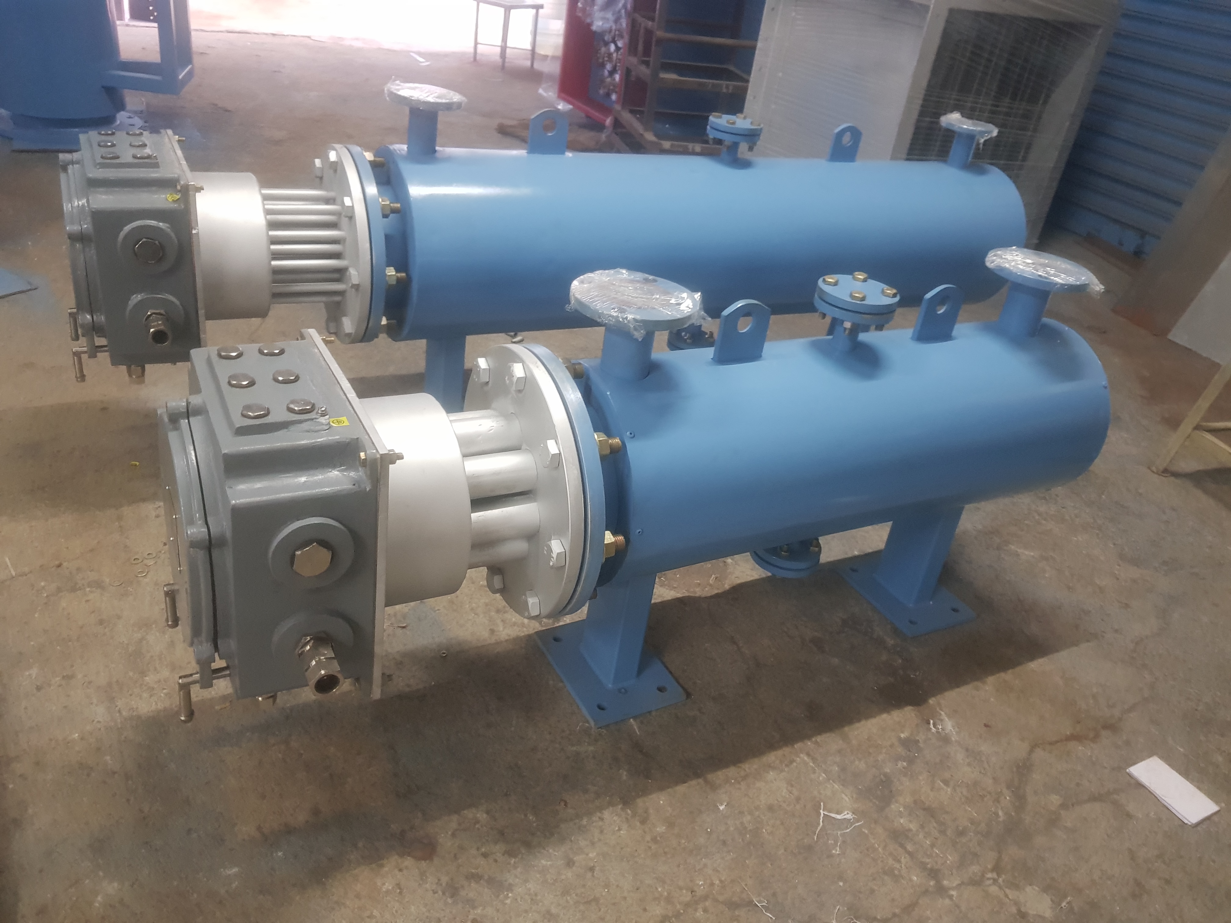
An electric heater simply converts electric energy into heat or thermal energy. This thermal energy is then transferred to the workload raising its temperature. There are many types of heaters for many different applications. Some heaters heat workloads using conduction such as a cartridge heaters (Figure 2). Heat transfer to and through the workload takes place by conduction. Some heaters heat liquids or gases via convection such as an immersion heater (Figure 3). Finally, some heaters heat the workload using radiation such as a radiant panel (Figure 4).
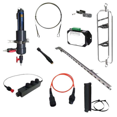
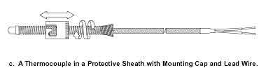
The Temperature sensor measures the temperature of the workload. It then sends a signal corresponding to that temperature to the temperature controller. As the temperature changes, the sensor signal also changes. The controller uses this information to decide whether or not to add heat to the workload. There are various types of temperature sensors, but by far the most common type is the Thermocouple. A thermocouple sensor is usually encased in a metal tube or sheath for protection (Figure 8). Sometimes a plug or other connector is attached to the lead wire for ease of wiring.
Temperature controller is used to ensure that the workload is maintained at the proper temperature. After the controller receives the sensor signal, it compares the actual workload temperature to the desired temperature (called set point). If the workload temperature gets too high, the heater is switched off. If the workload temperature drops too low, the heater is switched on. This "on/off" switching regulates electric current to the heater and thus work load temperature. Temperature control examples are shown in the figures below.
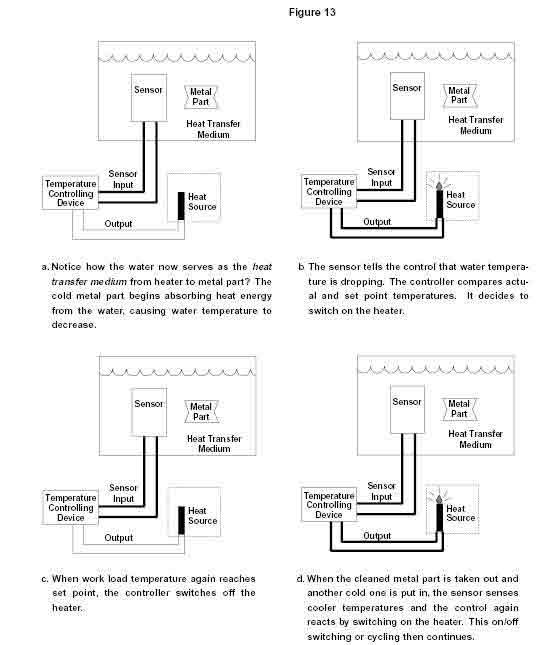
Now that we know a little about the four parts of a thermal system, let's observe a thermal system in action. In Figure 12a, the workload is a tank filled with water and a mild cleaning solution. A sensor is placed in the water to monitor water temperature. The sensor is connected to a temperature controller. A heater is also connected to the temperature controller and placed under the tank. What happens when the thermal system is switched on? What do you suspect? Read the captions in Figure 12 to find out!
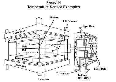
We have just observed a simple thermal system in action! It is true that thermal systems do get more complex than this simple example (like Figure 14). However, you will AWAYS understand how a thermal system is working if you keep things simple! Break it down into its component parts: work load, heater,sensor and control. Observe what each part is oing and how it is doing it. This makes you very valuable to the customer, because you can offer better solutions through better analysis.
Thermal Systems and Electric Heaters
The purpose of the heater in a thermal system is clear - to provide heat energy to the work load. What of the heater itself? How does it generate heat? What materials are used and why? What determines heater life? Lets find out! The four basic parts or components of a heater (As shown below) are the resistance element, the insulation, the Sheath and the termination.

Resistance Element
This is the "heart" of an electric heater! The resistance element is usually in the form of a small diameter, metal alloy wire or flat, thin ribbon. When a heater is connected to an electric power supply, electricity flows through the resistance wire. The wire resists the flow of electric current through it. This converts electrical energy into heat energy, causing the Resistance element to get very hot. That is how heat is generated in an electric heater.
An everyday example of this can be found in your toaster at home. If you look inside it, you will see a resistance wire strung along the sides. When you push down on the toaster's lever, within a few seconds these wires are glowing red. The heat generated by these wires is what browns (or burns!) the bread. You are witnessing live and in color an electric heater in action! The resistance wire most often used in industrial applications up to around 800oC is an 80% nickel - 20% chromium composition. We refer to it as "Nichrome". MATRUSREE uses Nichrome as well as Kanthal because of its superior ability to withstand high temperature operation and last for a long time. Even when using Nichrome wire, all heaters eventually fail or burn out. A heater will often fail if damaged or contaminated with chemicals, for example. However, what determines heater life. if none of these problems are present? Excellent question! Let's take up the challenge and find out! At high temperatures, oxygen inside of the heater chemically reacts with the resistance element (Figure 17). This causes a hard oxide coating to form on the wire. The oxidation process continues until the wire eventually disintegrates or burns through.
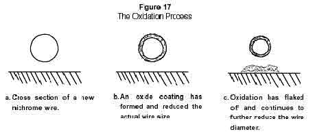
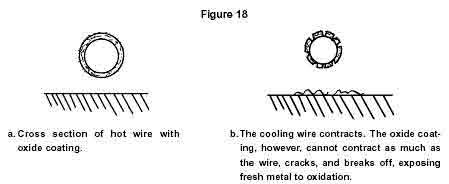
Simple, isn't it? Now here's the kicker. If the wire is operating at a constant temperature, the hard oxide coating actually slows the oxidation process. This, of course, extends heater life. However, in the vast majority of industrial applications, the wire temperature is not constant. Lots of equipment are started up and shut down at least once a day or more, for example. More importantly, the temperature control switches the heater "on and off" frequently. All of these things Cause resistance wire temperature to rise and fall. This heat up/cool down cycling of the heater causes the resistance wire to expand and contract. Expansion and contraction cracks the hard oxide coating on the
wire and exposes more metal to oxygen attack (Figure 18). The result? Temperature cycling greatly accelerates the oxidation process and causes the wire to burn through much more quickly.
Now, you may ask, what can we do to stop this oxidation process? Well, we can't really stop it, but we can easily slow down the oxidation process. One easy way is to reduce the operating temperature of the heater by using a lower watt density. Another way is to use sophisticated controllers to reduce the temperature cycling of the resistance wire. Another method to slow oxidation is to use a larger diameter wire. This extends the amount of time a wire can operate before oxidation.
Eventually eats through it. What else can we do? How about using a wire with higher temperature capabilities? That's a great idea! An example of this is an iron-chromium-aluminum alloy. This wire is used in ceramic fiber heaters up to about (12000C) or so. The aluminum in the alloy forms an aluminum oxide coating on the wire that greatly slows the oxidation process.
Note: Remember “watt density”? Watt density is the amount of power being produced per square inch of heated surface area. The more power we put in per square inch, the hotter that the resistance elements operate. That’s why reducing watt density on a heater reduces the resistance wire temperature.
Insulation
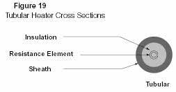
Insulation in an electric heater is used for a good reason: it electrically insulates the resistance element. Figure 19 shows a cross section of two types of heaters to illustrate where the insulation is. Note how insulation "isolates" the resistance Wire from the metal protective tube or sheath surrounding it. This prevents electric current in the resistance wire from jumping to the sheath and shorting out the heater. It also prevents someone working on a piece of equipment from getting an electric shock.
Good electrical insulators are called dielectrics. The amount of electric current an insulator lets "leak through" at a given voltage is called its dielectric strength. For example, a heater may "leak" or let through something less than 0.1 amps at some 1000 volts. MATRUSREE tests a heater's dielectric strength using a High Voltage Test (or Hi-Pot Test) on all its heaters to ensure that their dielectric strength meets the minimum standards.
Unfortunately, most good electrical insulators (or dielectrics) are also good Thermal insulators. This can cause the resistance wire in a heater to operate at Higher temperatures and burn out more quickly. How do we overcome this insulation problem? MATRUSREE uses insulation materials, which have the best combination of high dielectric strength and good thermal conductivity. In fact, these materials are so good that only a thin layer is required to electrically insulate the heater. A thin layer of insulation helps heat transfer from the resistance wire to the sheath (and on to the work load) much easier. There are many kinds of insulating materials used in heaters. For now, we will focus on two common ones: mica and magnesium oxide.
Mica :
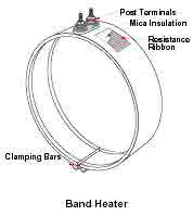
Mica is a mineral that is mined from the earth. It is then processed with a binding agent (a type of glue) to form flat, thin sheets. These mica sheets are then inserted between the resistance element and the outer metal sheath of a heater to electrically insulate them from each other Generally used in Mica Band Heaters Mica insulation has a maximum temperature limit of about 5500C At this temperature, the binder starts deteriorating and the dielectric strength of the mica begins to weaken. This deterioration eventually leads to a short circuit between wires or from the wires to the sheath. Therefore, the maximum recommended internal heater temperature for mica products be at about 5500C. This provides some safety margin.
Magnesium Oxide :
Magnesium oxide is the oxide of the metal magnesium. Magnesium oxide, known as "MgO" or "mineral insulation", is a fine, granular powder in bulk form. It is "filled" between the resistance element and the heater sheath. In all MATRUSREE heaters, MgO is compacted or compressed into a thin, solid layer. Refer back to Figure 19 for example of heaters using MgO insulation. Using compacted MgO let’s, us take advantage of its good thermal conductivity and great dielectric strength. MgO has an upper useful temperature limit of well over 2000ûF (1100ûC). This is usually never reached, because the Nichrome resistance wire has a much lower operating temperature of about 1600ûF (870ûC). MgO is great stuff, but has one major disadvantage - it is hygroscopic. Hygroscopic means that MgO absorbs any humidity or moisture that comes in contact with it. Moisture reduces MgO s dielectric strength and allows more electrical current to pass through. If enough moisture is absorbed, the resistance element could short out to the metal sheath and destroy the heater or blow machine fuses. To prevent this from happening, MgO is kept out of direct contact with air as much as possible and is heated to evaporate any moisture. The ability of a thin layer of insulation to resist current flow, yet allow quick heat transfer, helps MATRUSREE build efficient, high performance heaters.