Type 304 Stainless Steel sheath provides physical strength and resistance to high temperatures of up to 1200°F (650°C) and chemical corrosion. Helically wound resistance wire coil made from nickel-chrome wire is evenly stretched and precisely strung through the ceramic insulator, providing uniform heat. A custom mixture of several high purity magnesium oxide grain sizes, chosen to increase thermal conductivity and dielectric strength, are used to fill all remaining space inside and around the ceramic insulator. Channel strip heaters are available with or without mounting tabs. If without, the ends are silver soldered shut to prevent moisture and contaminants from entering the heater. The nickel-plated steel fins (SS optional) are mainly used for both forced air in a duct and natural convection air heating in a cabinet type oven.
Ceramic Insulated Finned Channel Strip Heaters are ideal for both forced air in a duct and natural convection air heating in a cabinet type oven.
Type 304 Stainless Steel sheath provides physical strength and resistance to high temperatures of up to 1200°F (650°C) and chemical corrosion. Helically wound resistance wire coil made from nickel-chrome wire is evenly stretched and precisely strung through the ceramic insulator, providing uniform heat. A custom mixture of several high purity magnesium oxide grain sizes, chosen to increase thermal conductivity and dielectric strength, are used to fill all remaining space inside and around the ceramic insulator. Channel strip heaters are available with or without mounting tabs. If without, the ends are silver soldered shut to prevent moisture and contaminants from entering the heater. The nickel-plated steel fins (SS optional) are mainly used for both forced air in a duct and natural convection air heating in a cabinet type oven.
FINNED CHANNEL STRIP HEATERS SPECIFICATIONS
CONSTRUCTION STYLES
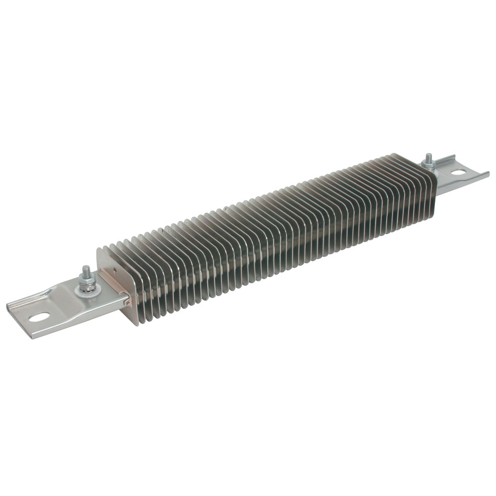
Finned Channel Strip Heater with Mounting Tabs
Heaters are designed with Nickel-plated steel fins that are mounted to the rectangular tubing (Stainless Steel fins are optional) and mounting tabs.
ELECTRICAL TERMINATIONS
Type T1: Screw Terminals at each end
10-32 Screw Terminals at each end
Type T2: Screw Terminals at one end
10-32 Screw Terminals (Tandem) at one end
Type T3: Screw Terminals at one end
10-32 Screw Terminals (Parallel) at one end
Type T4: Screw Terminals at one end
10-32 Screw Terminals offset (Diagonal) at one end